![]() Tel:+86 135 7086 9158
Tel:+86 135 7086 9158
![]() Tel:+86 135 7086 9158
Tel:+86 135 7086 9158
PRODUCT LIST

|
|
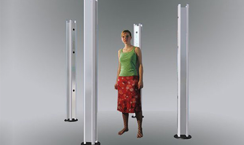
bodySCAN3D, 4 million pixels
Technical index The system has 4 columns, each column is equipped with 1 projector and 2 industrial-grade CCD Dimensions W 3.000 x D 2.230 x H 2.440 mm Sensor Monochrome/color CCD camera, GigE Camera resolution 8 x 2.336 x 1.752 Pixel Projection technology Micro-structured light projection technology Light source 50 W LED White Light intensity 300 ANSI Lumen Number of rasters 128 The shortest capture time is 6 sec (3 sec fast scan mode) Scan head weight 4 x 40 kg Power supply 4 x AC 110/220 Volt, 50 – 60 Hz Controller 4 x 150 W, USB 2.0 Operating system Windows 7 64 Bit Field of View Scanning angle: 20-30 degrees, working distance: 1.870 mm Field of view[mm] (1) 2.300 Scanning area[mm] (2) 2.000 x 1.200 Depth of Field [mm] (3) 800 Resolution in x,y direction[µm] (4) 0.5 Extreme Z direction[µm] (5) 0.08 Noise (z)[µm] (6) ± 0.04 Characteristic accuracy [µm] (7) ± 0.15 Note: The bodySCAN3D measuring system is defined in a cube arrangement, with four independently measurable and defined measuring heads. Each probe is composed of 1 projection and 2 high-end industrial cameras. Of course, you can add additional probe units to the system for complex picture stitching. Arrangement: Please note: All data in these tables is based on a single scan. These data are the average values of the middle part of the scan range, which are obtained after a given scan environment and precise calibration. These data are only valid if the software and hardware equipment provided by Borkoman and the corresponding system settings are used. All accuracy and resolution details will be affected by the surface material of the object and the environment. (1) All data in these tables are average values. Within a rough range. The diagonal length of the field of view may vary by plus or minus 10%. (2) The scan range size on the plane. (3) The maximum depth in the Z direction. (4) The horizontal resolution is a theoretically calculated value (the calculation is based on the field of view and the resolution of the camera chip). (5) The calculation of this extreme value is theoretically achievable precision extreme value, based on phase calculation and 128 gratings. (6) The measurement of noise ratio is based on the relationship between the actual scanning point distribution and the best fit curve. The noise of the scanned 3D data has a lot to do with the noise of the camera chip. (7) The characteristic accuracy is defined according to VDI 2634. |
Copyright © Shenzhen Airboat Technology Co., Ltd. All rights reserved 【Backstage management】